
3D CAD Modelling
Parametric parts, assemblies, weldments and equipment models developed from requirements, sketches or legacy data.
Mechanical & industrial CAD
3D modelling, detail design, steel and fabrication drawings, CAD conversion and controlled documentation for machinery, plant equipment and industrial structures.
Discuss this scope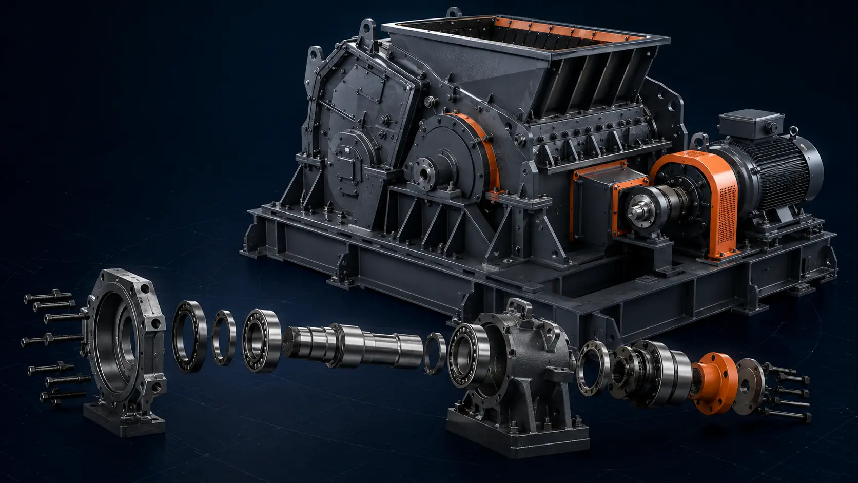
The engineering requirement
Industrial CAD work is not complete when a model looks correct. Interfaces must fit, welds and tolerances must be producible, access must be possible, bought-out parts must be controlled and drawings must communicate unambiguously to fabrication, assembly and inspection teams.
KURUKONDAR supports new designs, modifications and engineering-capacity peaks. We structure the CAD model, drawing hierarchy and review gates around the final use: concept approval, supplier enquiry, production, erection or lifecycle documentation. Our background in heavy industrial execution keeps details grounded in fabrication and installation reality.
Scope of work
Defined engineering outputs with the level of detail matched to concept, tender, fabrication or site execution.
Parametric parts, assemblies, weldments and equipment models developed from requirements, sketches or legacy data.
Dimensioned part, assembly and fabrication drawings with clear material, weld and interface information.
Frames, platforms, stairs, walkways, supports, connections and shop-oriented steel documentation.
Controlled updates to existing machinery and plant equipment around fit, function, access and manufacturability.
Migration of drawings and neutral formats into structured, maintainable CAD models and drawing sets.
Templates, model structures, drawing standards and repeatable workflows that reduce engineering inconsistency.
Engineering in context
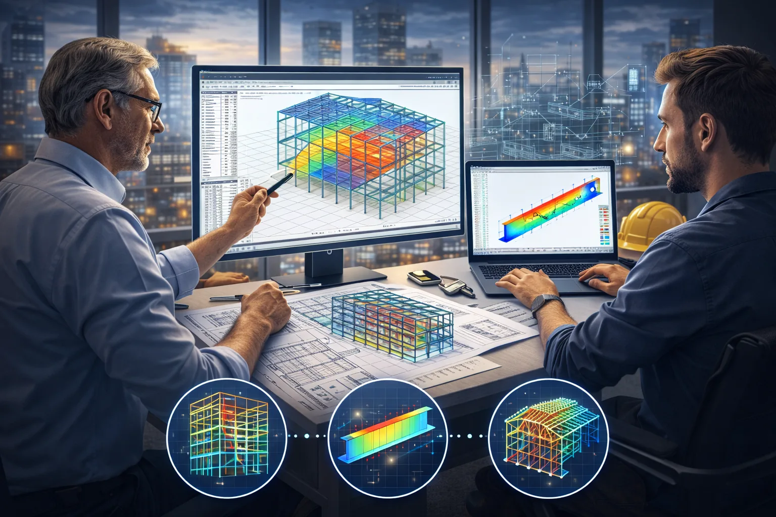
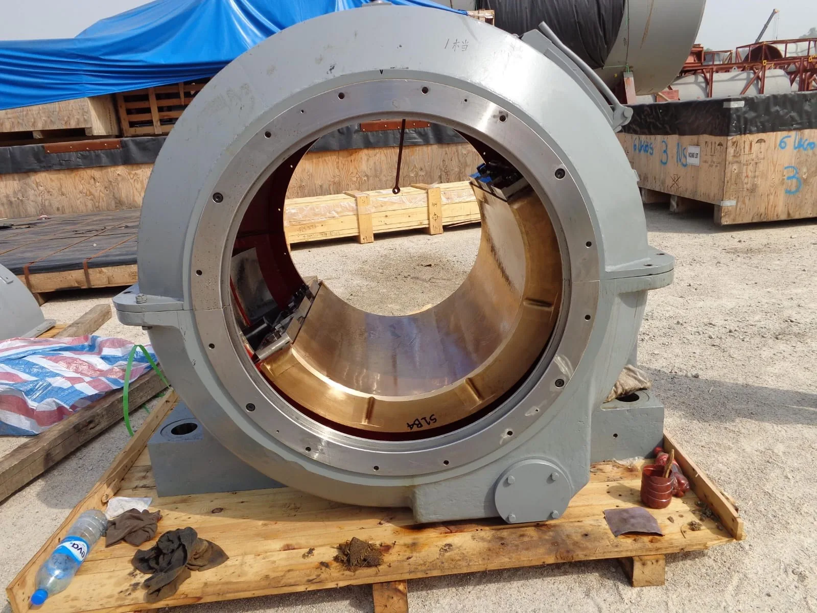
Purpose-specific visuals connect the digital model and analysis to the equipment, interfaces and site conditions they must represent.

Engineering output
Models and reports are structured for coordination, review and controlled handover—not isolated analysis.
Working method
Each stage closes a specific risk before the project moves forward.
Review geometry, specifications, standards, interfaces and the quality of legacy data.
Set model structure, datum logic, drawing hierarchy, ownership and exchange formats.
Develop geometry, resolve interfaces and check manufacturing and assembly implications.
Issue reviewed models and drawings with agreed status, formats and revision traceability.
Applications
Frequently asked questions
The existing KURUKONDAR toolchain includes CATIA, Siemens NX, Creo, SolidWorks, AutoCAD and HiCAD. The required native format, release and data-exchange workflow are confirmed for each project.
Yes. We can rebuild geometry from 2D drawings, scanned records or neutral formats. Missing dimensions and conflicts are logged rather than silently guessed.
Yes, when the scope includes detailed engineering. Drawing content, standards, weld information, tolerances, material definitions and approval responsibilities must be agreed before issue.
Yes. Support can be structured as a defined work package or as additional delivery capacity operating within your standards, review process and data environment.
Project review
Send the available inputs. We will identify what can be delivered, what is still missing and the practical next step.
[email protected] ↗Schaltstation 1